I always wanted a “pair of eyes” for my Home Assistant instance so I thought: Why not ? Let’s bring this in !
Goals:
- Playing a little bit and learning more about WiFi cameras
- Have some eyes around the house when I’m not home
- Monitor my sprinklers in case something goes wrong maybe
- Home Assistant integration and other automation on top of it
Prerequisites
A cheap WiFi camera should be fine as I don’t want detailed monitoring or ultra HD resolution. I stumbled across the TP-Link Tapo C100 and I bought it immediately as it had a very competitive price as well – around 30$. It offers motion detection and “night vision” as well so I thought why not ?
The camera:
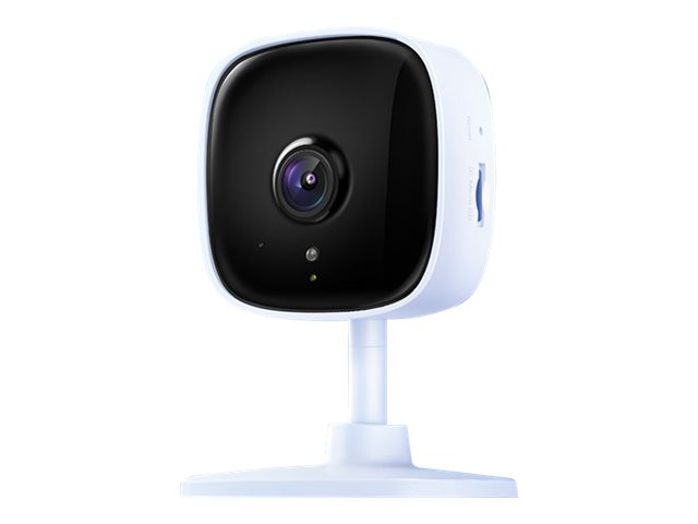
Pretty small device with some nice features packed in – great ! Let’s move on.
Preparing the stuff
Requirements:
- Should work outside and in rainy conditions as well (moisture and all the good stuff that’s out there in the wilderness)
- 24h availability if possible
- Low power consumption is a nice to have as well as this thing will be powered all the time
Building phase
The most awaited part – yess !!!
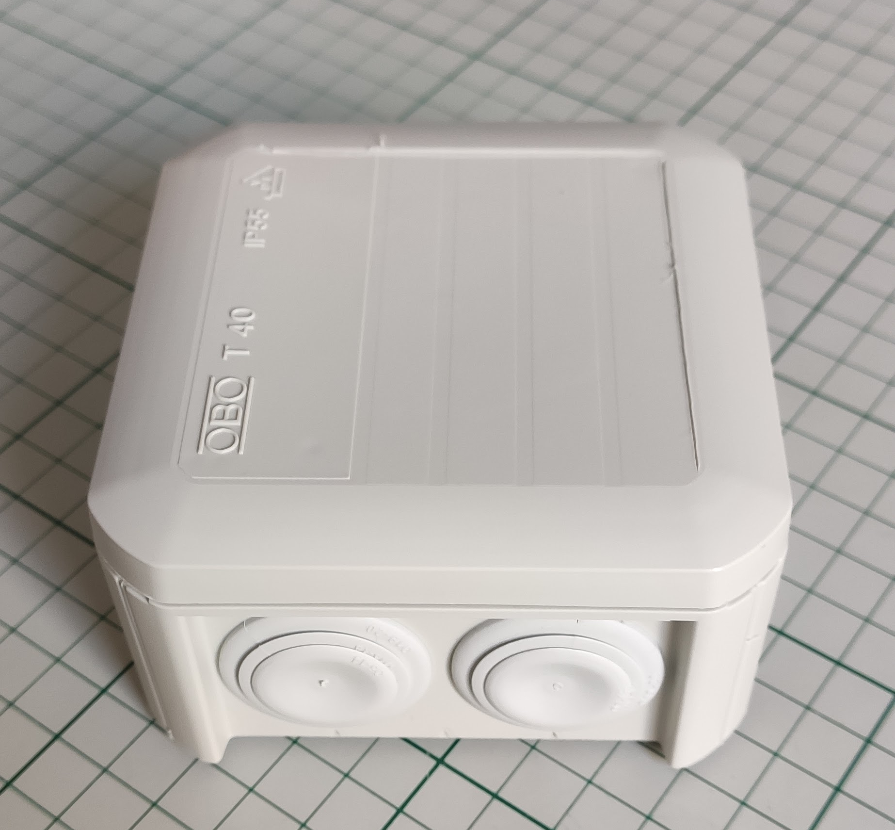
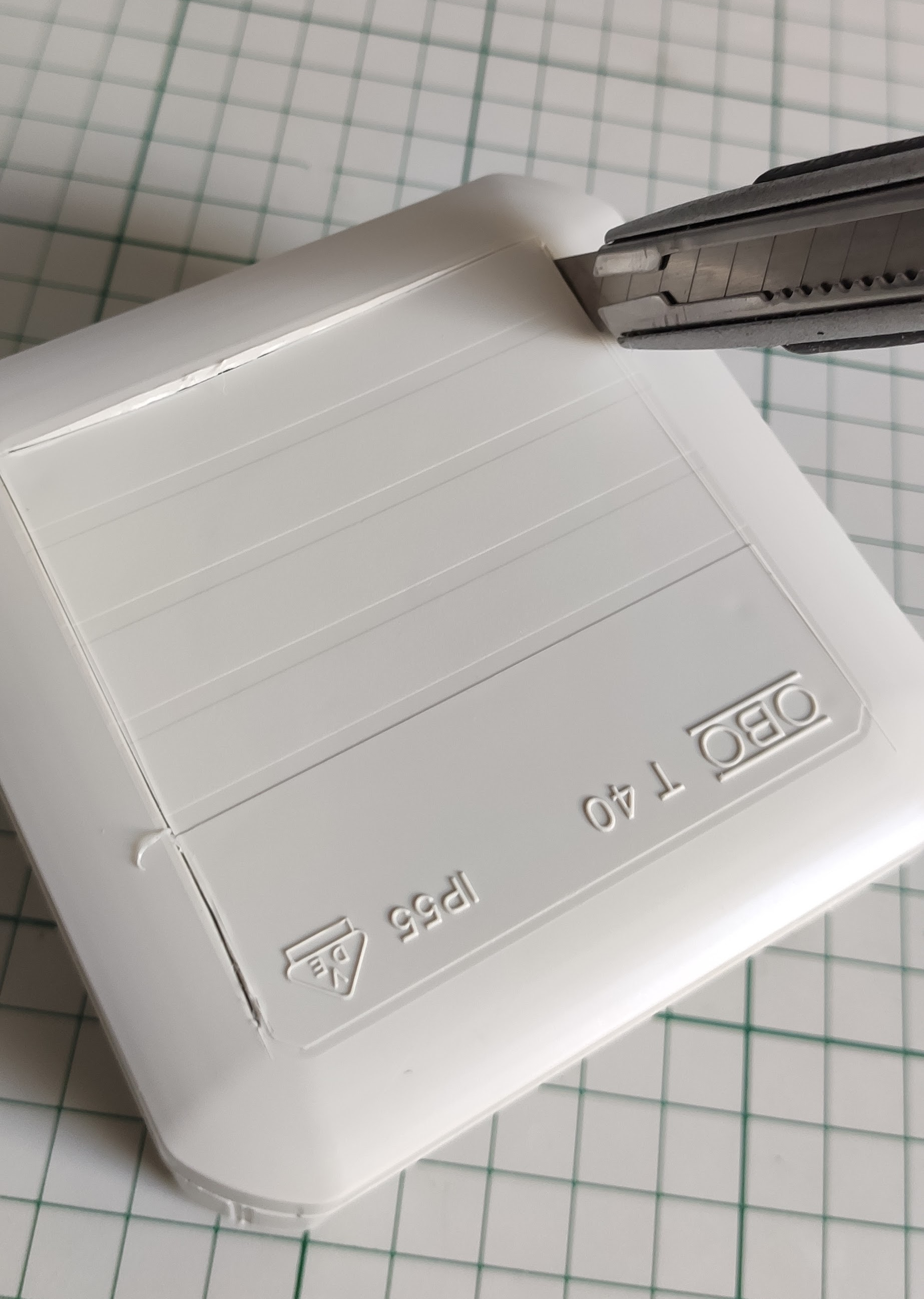
Initially I wanted a small junction box IP65 rated but I haven’t found one in the local store to fit the bill so I went with a IP55 which is not that bad after all. I don’t live in a stormy area so it should suffice theoretically – doing compromises ? We’ll see later if something goes bad – being a cheap camera I think we can accept this compromise and after all it’s not something that’s part of a vital system so yeah… let’s move on with the build.
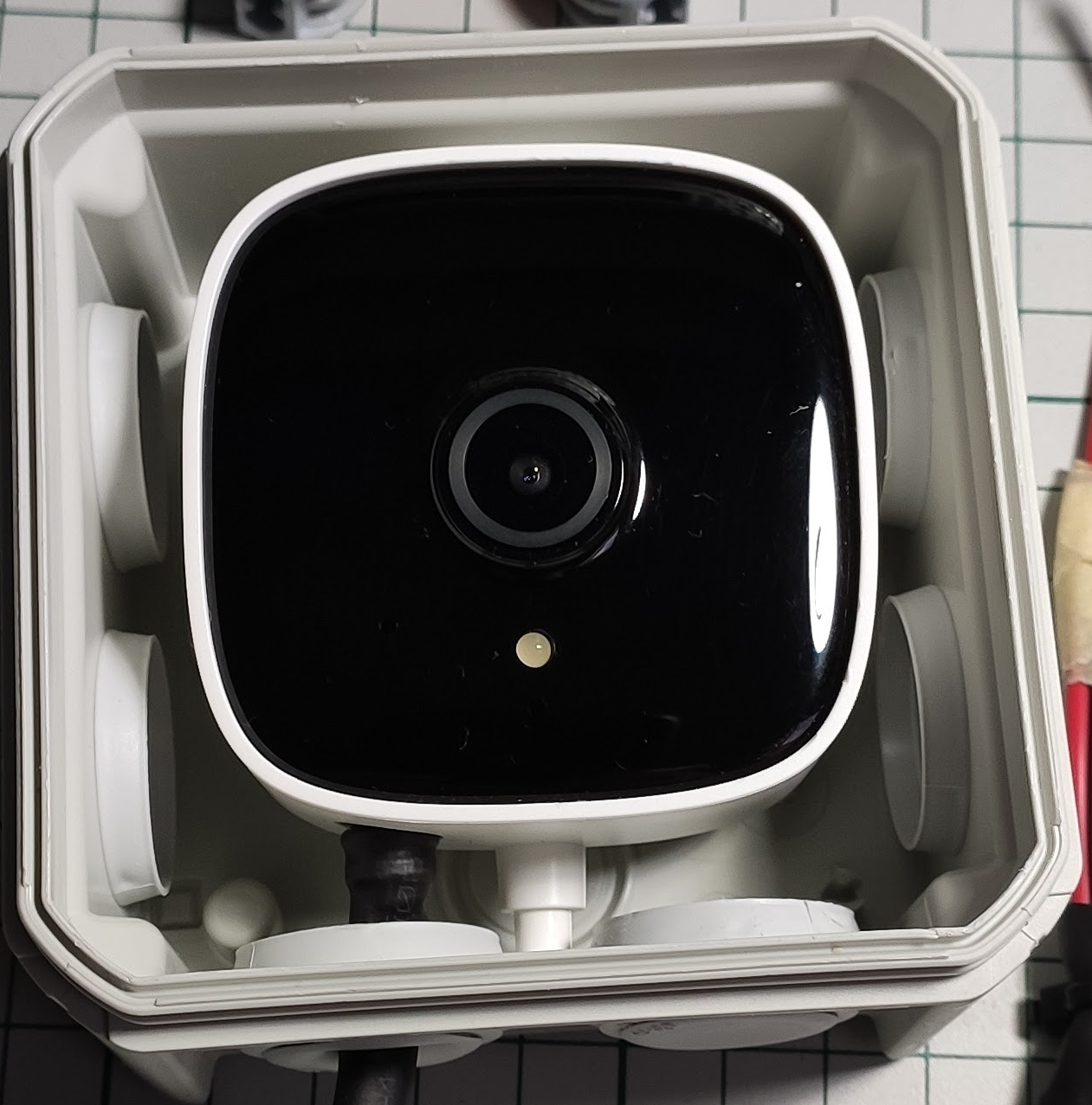
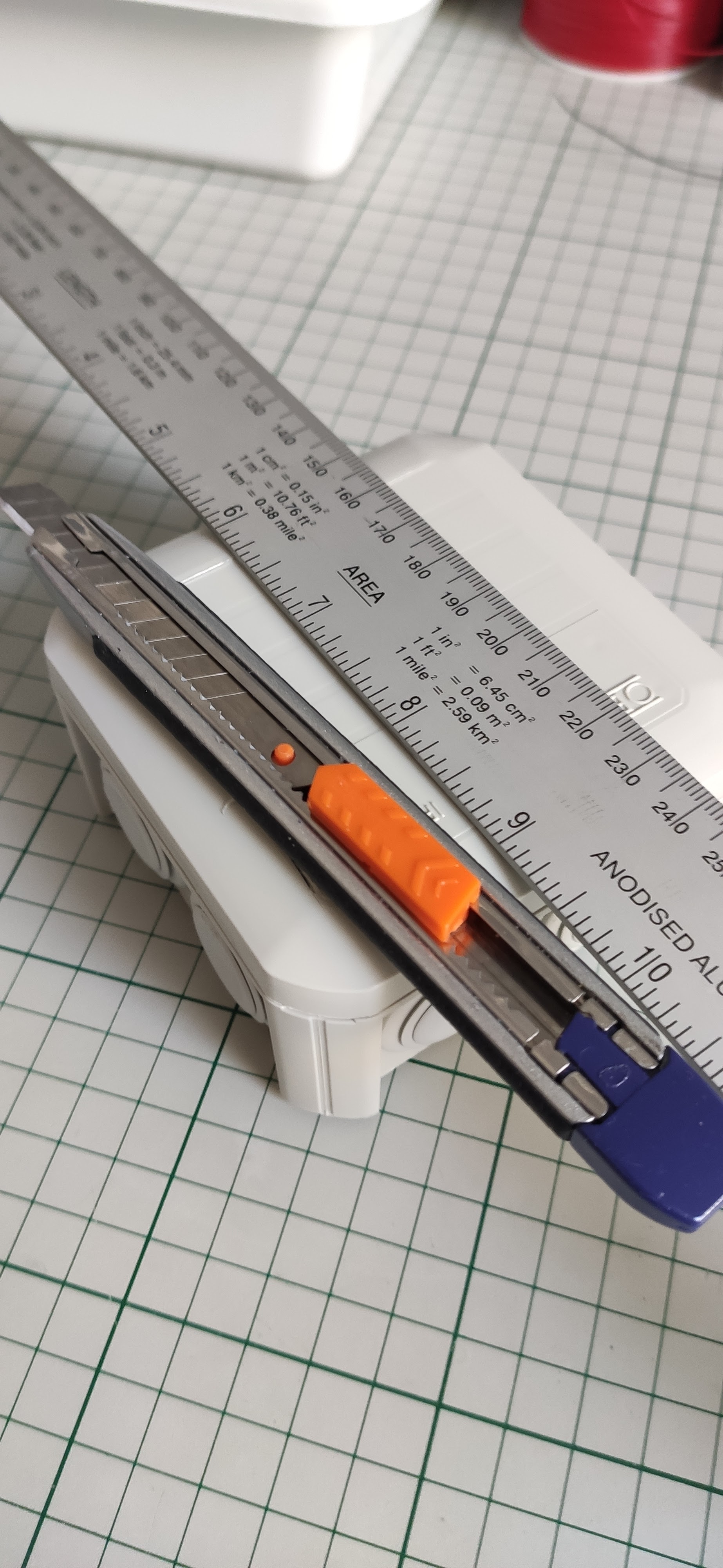
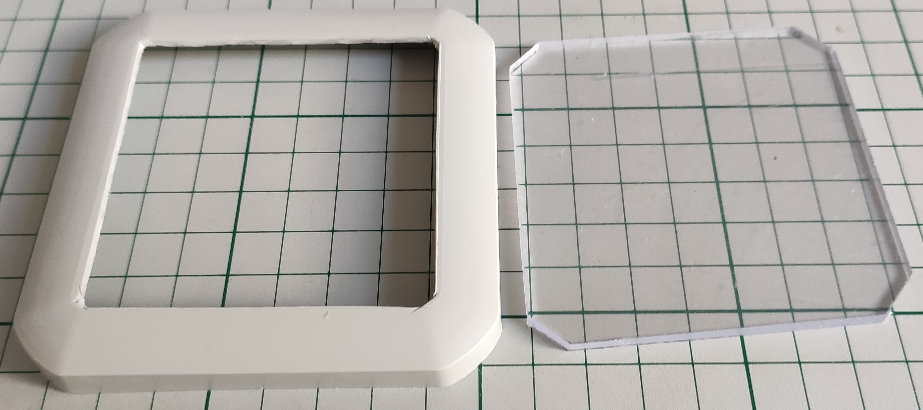
Preparing the enclosure: first let’s cut a window for the camera so that it can “see ” outside.
For the window and final assembly I used a piece of acrylic glass and glued it to the box lid:

For the moisture part I added a little bag of SILICA-GEL inside the box – will it keep it dry ? We shall see …
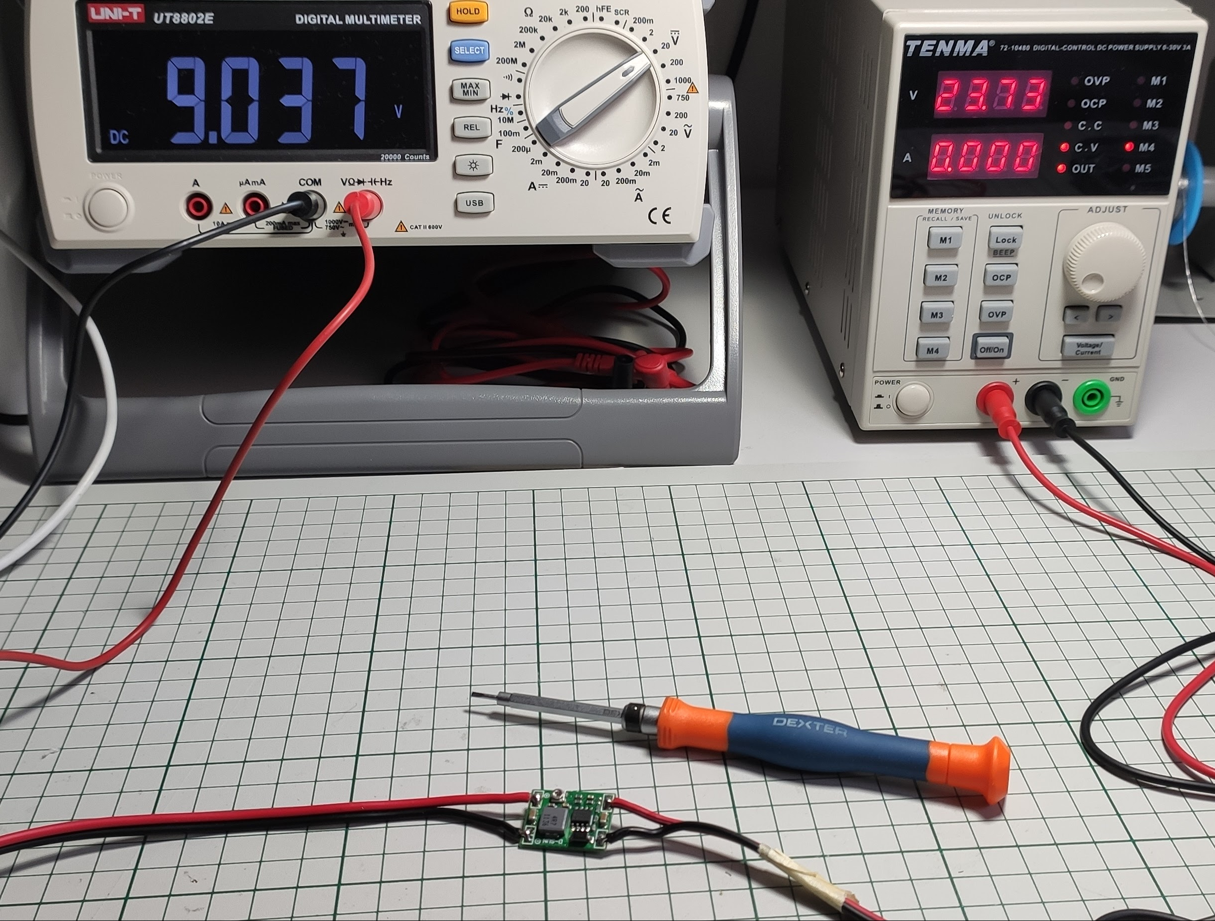
Next after the assembly was done I had to take care of the “electric” part – here I’m talking about powering this thing. The original power supply has an output of 9V/0.6A – continuous current of course.
I already have “power” available outside in another junction box which keeps alive my sprinklers automation (another self made project that I will talk about later in another post). So all I have to do is to steal some power from there.
I did the math first in order to see if we have enough juice for all – the camera takes around 1 – 1.5W of power on average which is pretty damn low. Let’s take around 2W into consideration as a maximum.
The sprinkler valves are rated at 24Vac and 370 mA inrush, 210 mA holding as specified by the manufacturer. This means that initially one valve draws around 24V x 0.37A ~= 9W real power and then it settles to 24V x 0.21A ~= 5W. So my power supply should be able to withstand in the worst case a peak power draw of about 9W + 2W = 11W. The previous math assumes that one valve is running at a time which happens to be my case. I have two zones that need watering but I cannot water them both at the same time because there’s not enough water pressure hence the previous mention.
Now the transformer that I bought long time ago is a TEZ30/D/24V – 30VA rated. Yes I know, I know that is apparent power and it’s not quite the real power. Depending on the load if it’s reactive or not we also have a reactive part of course. The valve solenoid is reactive obviously because it’s a solenoid so there’s reactive power present as well. The manufacturer gives us the current drawn but is it the real part or the apparent/virtual one? Not very clear – but if I remember well when talking about AC stuff and this valve is rated for the AC part I assume that’s the apparent value.
So the above power rating for the valve should be 9VA and not 9W. Apparent power is always bigger than real power so if we take this into account then with a 30VA rated transformer we’re on the safe side. I neglected the 2W of power drawn by the camera – why ? Well because is so little compared with what the rest of the circuit draws so again we’re on the safe side.
OK so my transformer delivers 24Vac which gets rectified and that gives around 34 -35V of DC voltage. I need a DC-DC converter of course because it’s more efficient when it comes to lowering voltages of this level of magnitude. If using a classic linear voltage regulator to get from 35V to 9V oh well… that means (35V – 9V) x 0.2A = 5W !! Ouch that’s a lot for a linear voltage regulator to withstand – lots of heat – not good ! And another important aspect: it dissipates lots of power that’s not needed – much more than the load (camera) requires !!!
Note:
The 0.2A from above was computed from observation (I could insert an ammeter in the real circuit and get the exact value but I was lazy). I noticed that the camera draws about 60mA when powered via the DC-DC converter from a 24Vdc source which means: 24V x 0.06A ~= 1.44W. This translates to a current draw on the 9V input from the camera of: 1.44W / 9V ~= 0.16A and I rounded up the value just to consider the worst case OK?
Now you know why I made the assumption that the camera draws around 1.5W of power on average – let’s not consider the power loss introduced by the DC-DC converter shall we? … because it’s smaller and we all know that DC-DC converters are pretty efficient ( well not on the whole range of input vs output voltages of course but again let’s keep things simple).
Phew… a lot of math and I don’t like math very much to be honest but it seems to be a necessary thing.
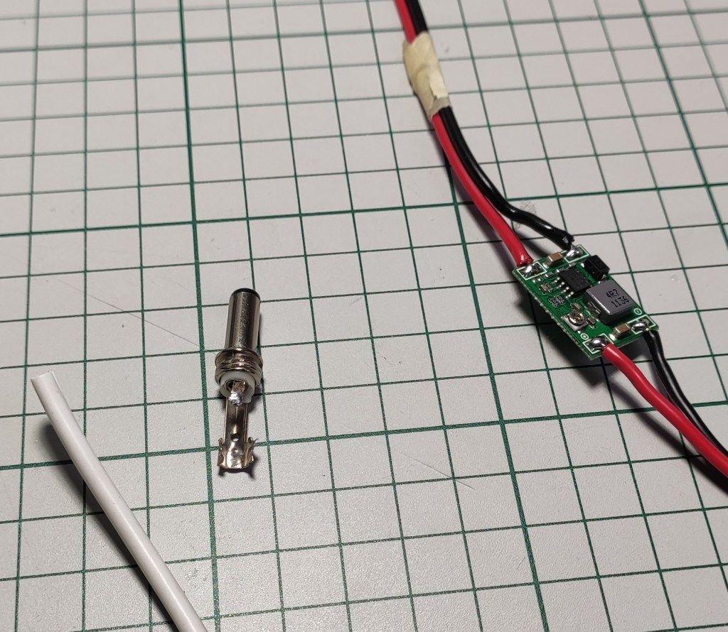
Tuning the DC-DC converter output to 9V:
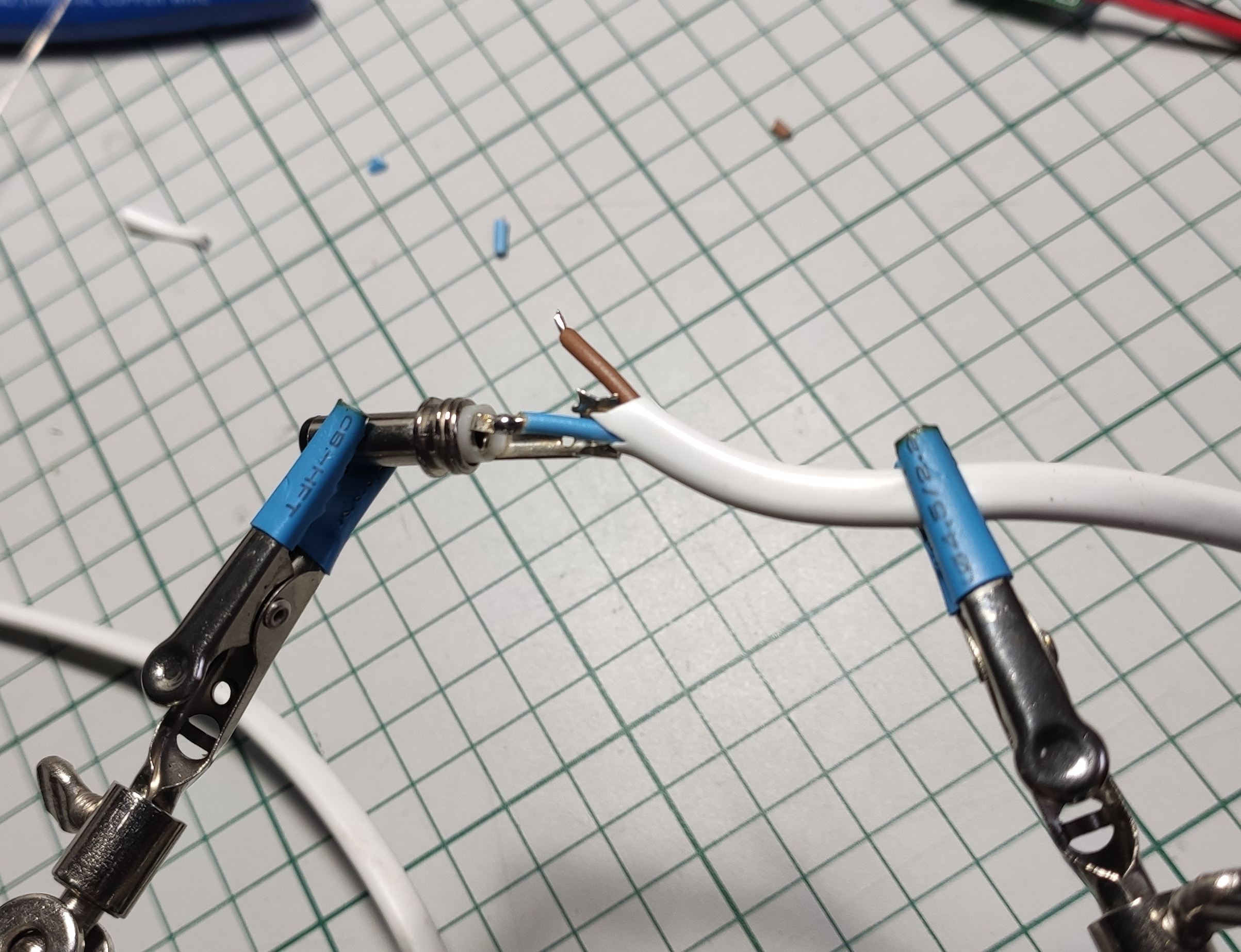
And the final piece – soldering the barrel connector:
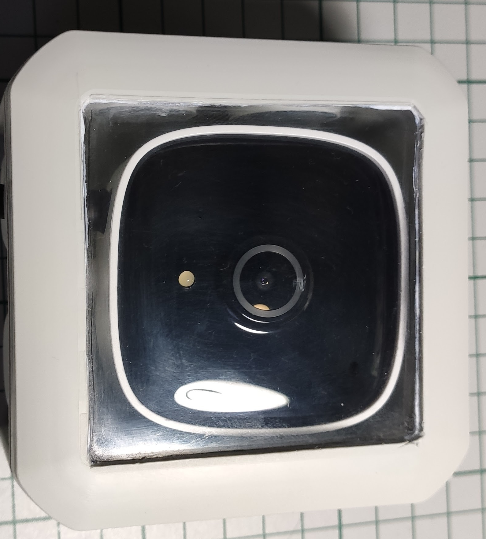
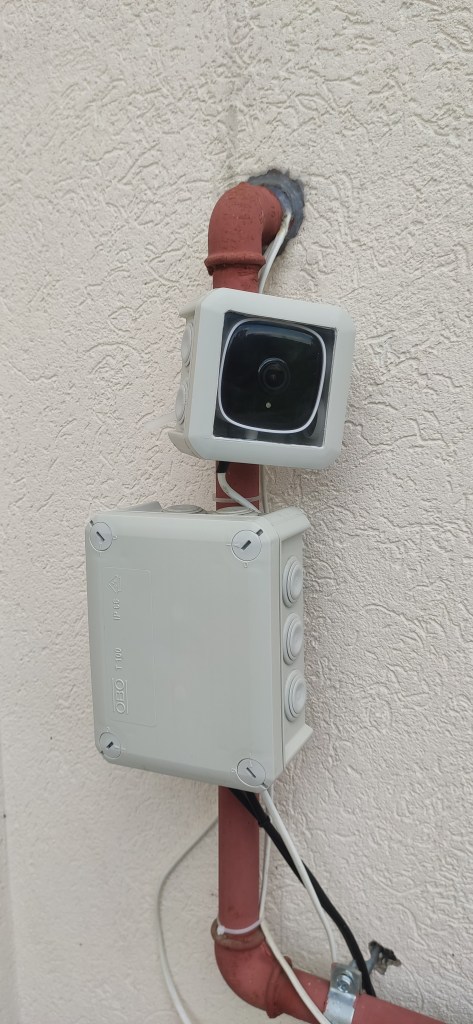
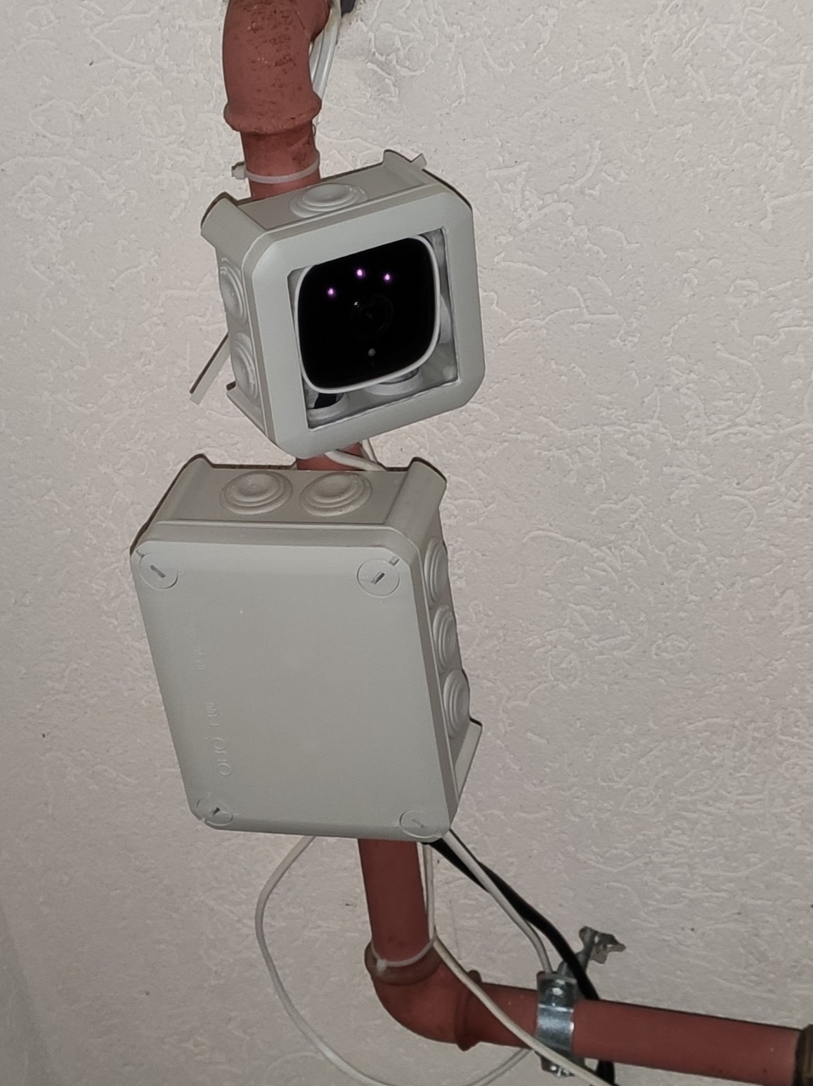
We’re getting close now to (on the right – night mode enabled) – ignore that little mess of wires for now:
The “software” part
The initial setup must be accomplished via the official Tapo application which includes: connecting to your home WiFi, setting the camera name, etc. After this part and/or other tweaks that you want to make inside the app the next part is the Home Assistant integration. The Tapo application is still required as far as I know if you want to perform firmware updates in the future and other stuff that is not accessible outside the app.
For the Home Assistant integration you need HACS installed and configured first. Then the Tapo: Cameras Control custom component must be added and configured. All the required steps are documented on the official Github page.
Note:
A camera account is required in order for the Home Assistant integration to work. This can be accomplished inside the Tapo application in the advanced camera settings (tap the camera -> the gear icon in the upper right corner -> advanced settings – > camera account). This is not the cloud account that you configured for logging into the Tapo application.
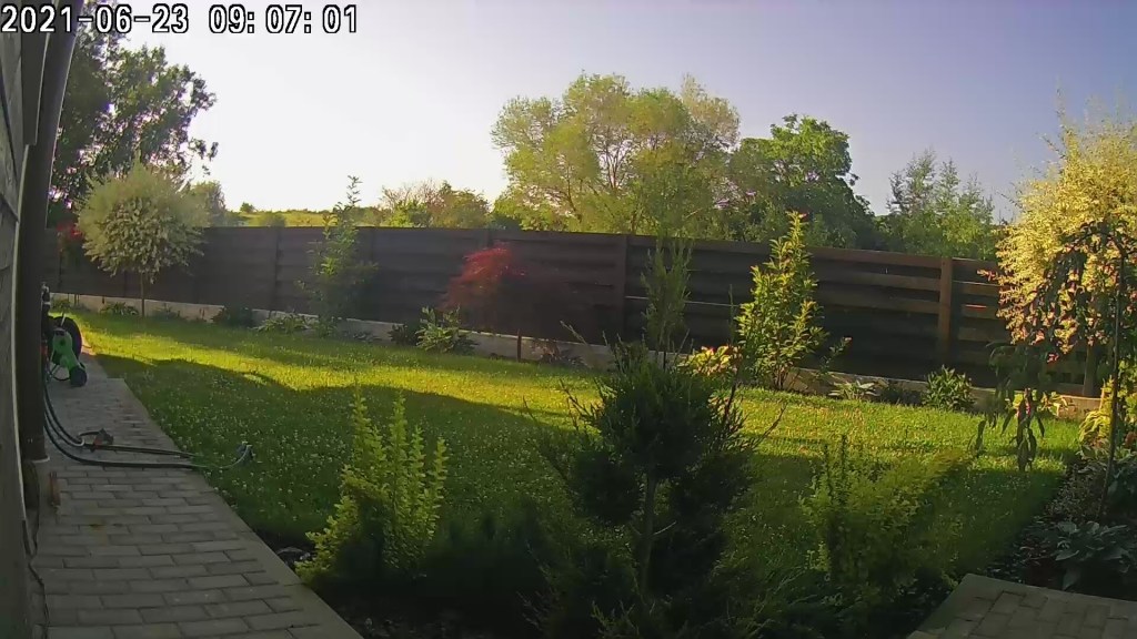
And the final result – live streaming:
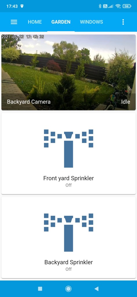
I also succeeded to add the video stream inside my “Garden” view from the Home Assistant dashboard and it works quite nice (it has a little bit of latency compared with the Tapo application but it’s OK as I don’t need details in this case).
Conclusion
I can further add other automation on top of it if desired because I also have motion detection available so… all in all I’m happy with the build and I consider it a success.
