In my previous post I talked a little bit about the switches I was working on and the required stuff in order to have a smooth integration with the existing infrastructure. And by infrastructure I mean the existing wiring present in the walls in the majority of the European countries.
What we’re after in the end? A light switch that works with no neutral wire and wireless communications. Also low power consumption is important – I’m sorry but no WiFi allowed!
I also mentioned about the Livolo switches and you may ask why… well because it was the first switch that I came across and that accomplished most of my requirements. It’s a modular design also and the first easy thing to do was to replicate the front plate.
The original is on the left side and my replica on the right for comparison:
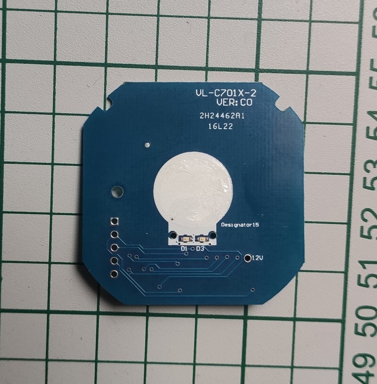
I wanted to do this because I needed a solution that fits in the wall and works only with the live wire. I also wanted to have wireless support of course.
And yes it worked but I wasn’t fully satisfied. Why? Because I had to buy an entire switch only to decommission the original front board and replace that with my replica. Of course it’s easier as you have all the parts in place and maybe cheaper.
But what if this switch will disappear one day or another hardware revision comes in and my replicated front board won’t fit again? This is not the only reason because I wanted to tune in the power supply also to my needs. And in the end why not have a full design for this piece of art and replicate the whole thing whenever needed. Make it also open hardware and give something back to the openhardware community. Let’s face it – this design is not something new and I didn’t invented it and most of the inspiration and knowledge that I gained from building it comes from the opensource community and/or articles published from various people/companies on the internet.
Continuing the above I have to mention about Power Integrations that helped/inspired me in building the so wanted power supply by studying their DER-622 publicly available document. And guess what? The power supply from the Livolo switches follows more or less the same design.
Other project that inspired me is the MySensors one and its great community – a lot of good folks in there with lots of knowledge.
OK let’s discuss now about each module from this switch.
Touch sensing/control module
This is the front board which the user interacts with via that stylish and glossy panel. It has a MCU on it with touch sensing support. Now I’m not going to explain here how capacitive sensing works as there’s plenty of documentation about that on the internet.
In my replica I added the well known RF SOC with Bluetooth support from Nordic Semiconductor and more specifically I used the NRF51/NRF52 series. I picked this one as it has the best support when it comes to firmware, compilers, etc. and it’s pretty cheap nowadays also.
Initially I used some ready made NRF5xxxx modules bought from AliExpress like PTR5518, HolyIOT. For touch sensing I used the Microchip MTCH10x capsense solutions which worked great also. Everything can be found on my GitHub page.
As I already mentioned in the previous post my first attempt for the radio/networking part was the MySensors project and the NRF24L01/RFM69 radio modules but with not so great success. I’m not saying that the MySensors project is not great or that it was because of it… I think it was a fault in my hardware designs and especially on the RF part which is kinda new for me when doing custom PCBs.
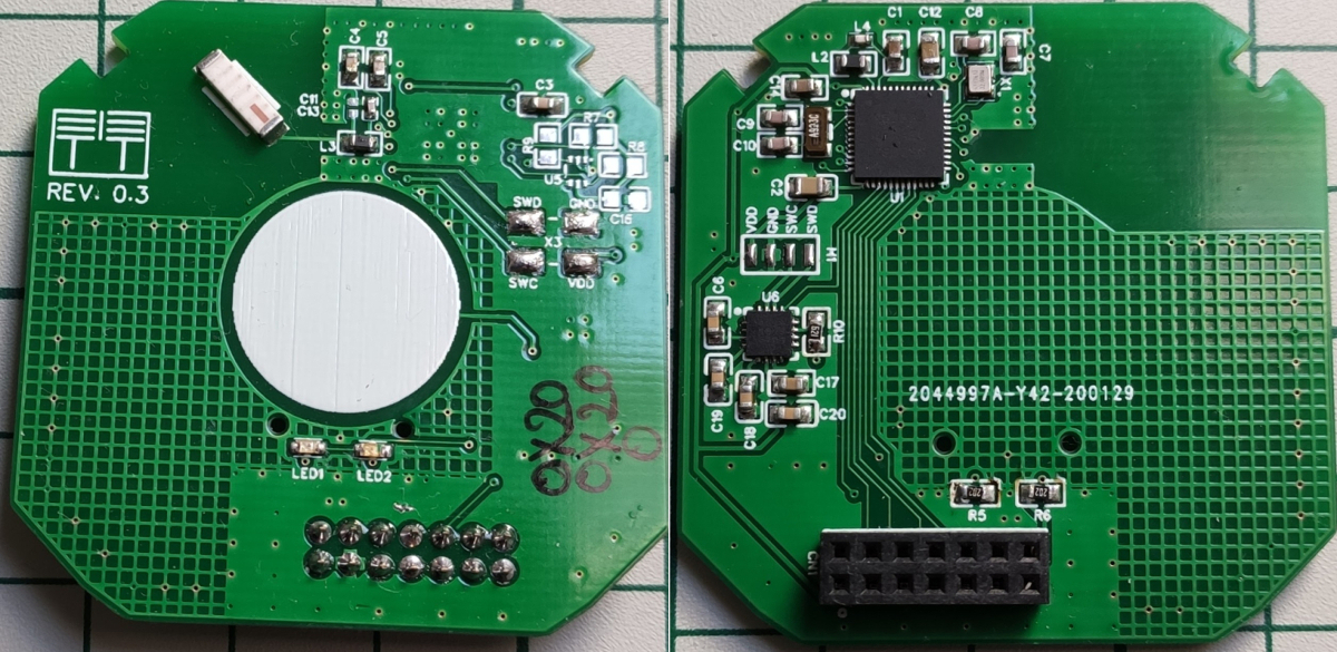
Yet again I wanted to learn and do more by going a little bit further and make my own variant so in the end this is the result:
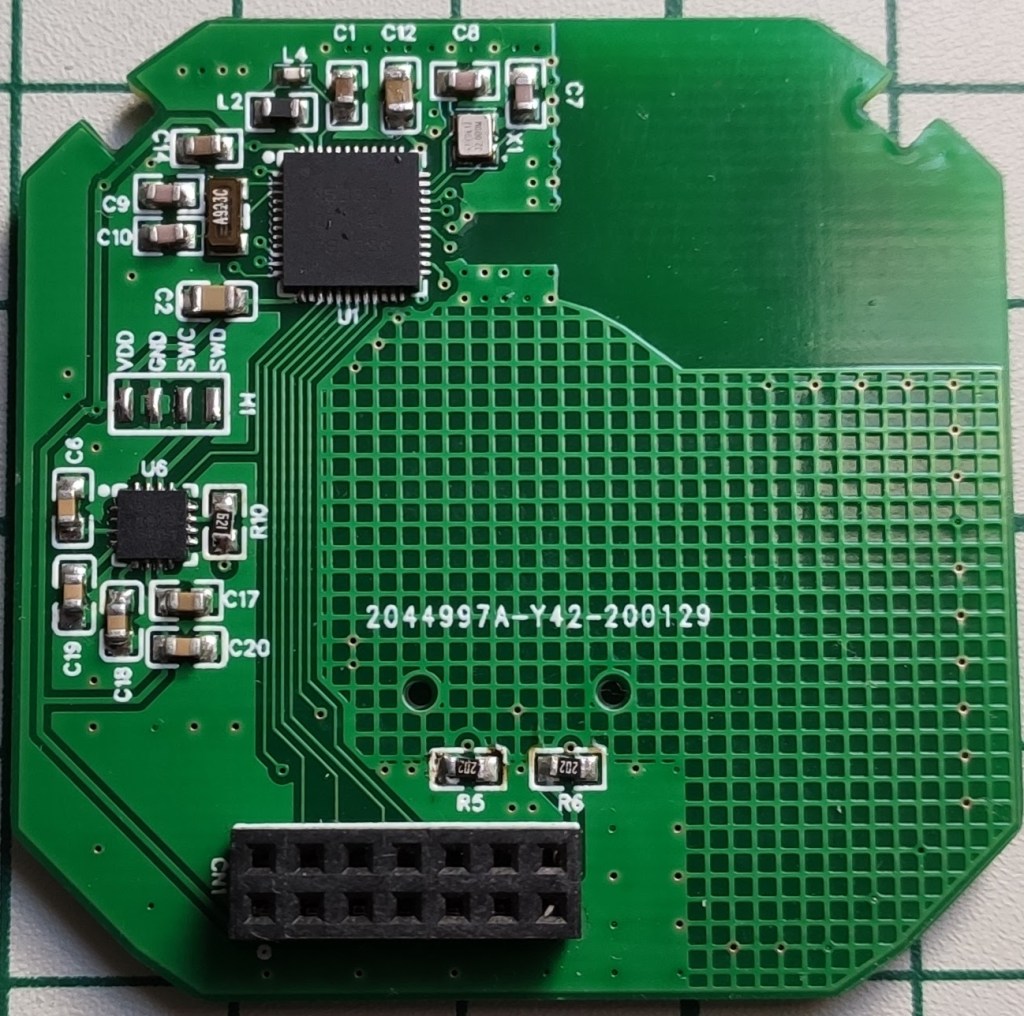
It’s a fully customized design now and we don’t need to rely on other vendors to buy their RF modules. Yes it implies more work but the final results are very satisfying. I also changed the touch sensing solution with Cypress Semiconductor ICs which are much better in my opinion. The final project can be found here (I didn’t mentioned but there’s also the two channel variant on my GitHub repository).
Ok so what we have so far is a custom module that has the following embedded:
- Touch sensing support (provided by the CY8C4014 chip)
- RF SOC powered by the NRF52832 chip – I ended using this one as has Bluetooth Mesh support also (more on that later)
Everything was designed using EasyEDA initially because I really love their ecosystem where you have everything in place starting from design to manufacturing and assembly – very powerful. I’m also a big fan of KiCAD of course but there are some things that I really miss in there compared to EasyEDA.
Schematics:
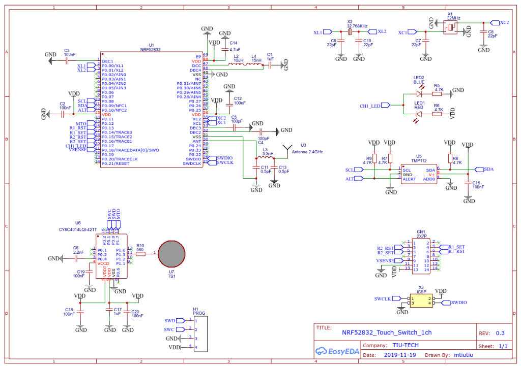
The heart of this hardware design is of course the NRF52832 chip from this great company called Nordic Semiconductor. They really have good solutions for building RF stuff (and no, I’m not an affiliate or doing promotions for them).
It’s a standard design based more or less on their recommended layout and application note(s). Of course this is my first RF custom design so it’s not perfect in regards to PCB layout and such but I tried my best to stick to the rules.
Next I used the wonderful IC’s of Cypress Semiconductor for touch sensing which in my opinion are best in class for this stuff. If you never heard of Cypress Semiconductor and of their PSOC solutions I do recommend you to do so – very powerful stuff (MCU and FPGA on the same die and a very powerful free IDE for doing the design).
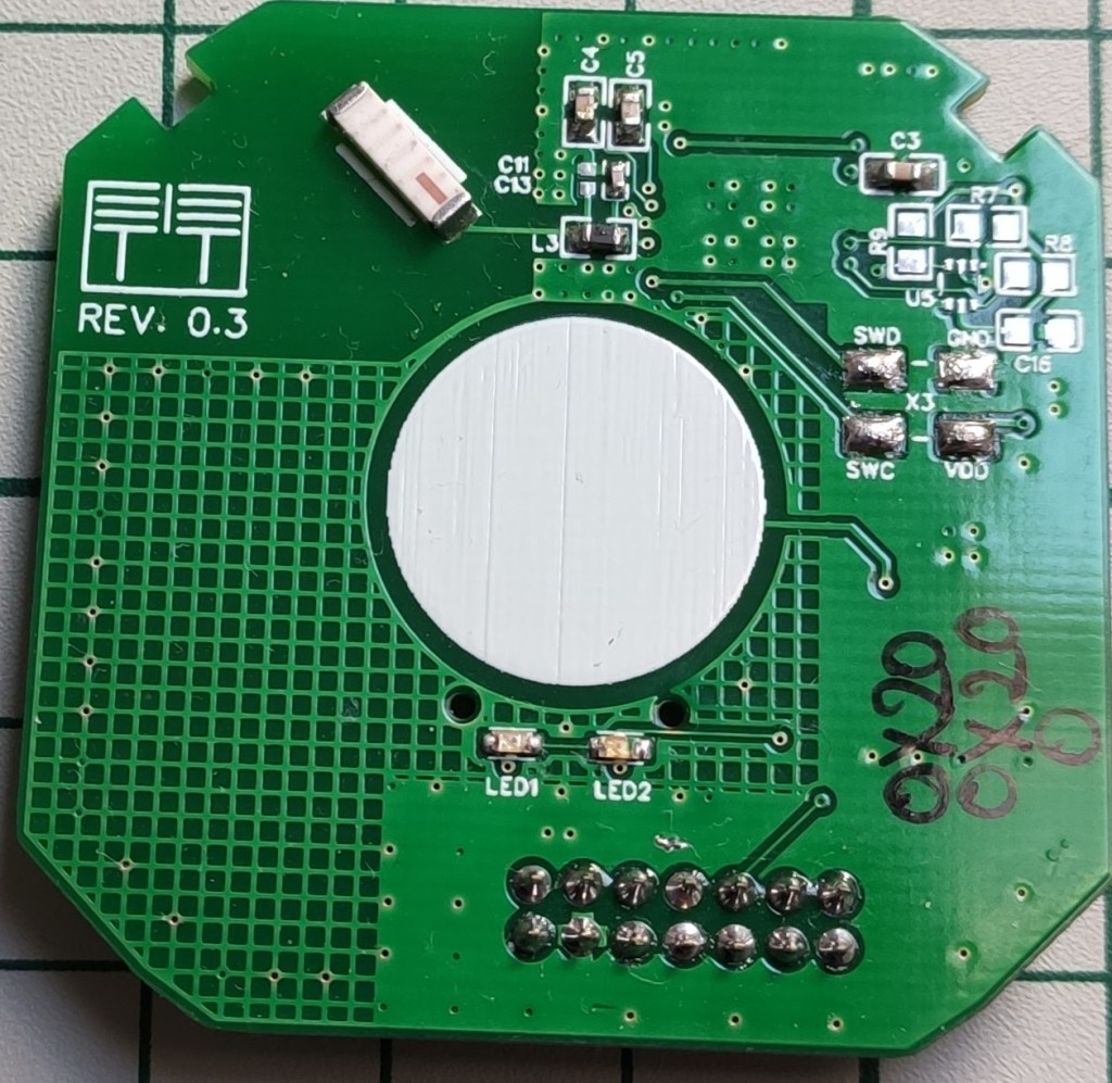
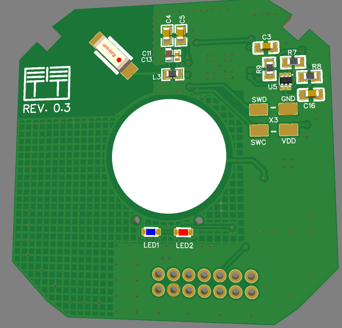
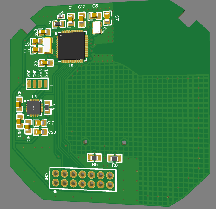
Front/Bottom side of the PCB layout:
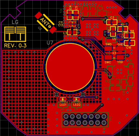
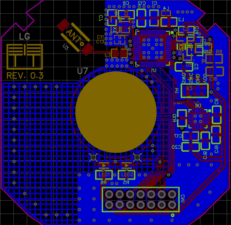
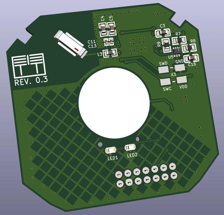
Some 3D renderings of the board:
I also ported this design to KiCAD (PCB only) using this very cool utility called easyeda2kicad.
Just for you to see how this project looks in KiCAD – Godlike!
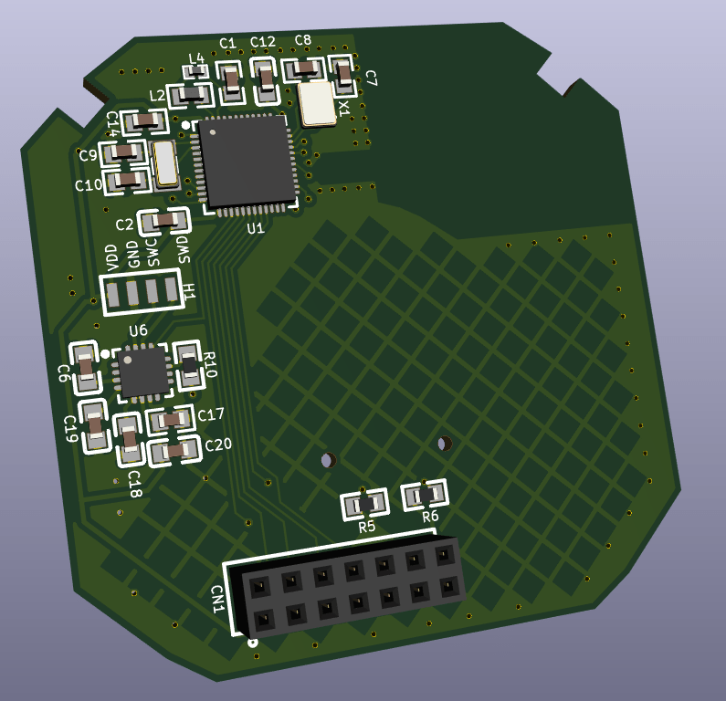
This is where KiCAD shines and it also offers other powerful features like STEP export for doing MCAD and 3D printing custom plastic enclosures (which I did for this project also).
Software
There’s a long story for the software side also going from using the Arduino/MySensors core and dedicated Bluetooth libraries to Apache MyNewt and Zephyr RTOS.
I won’t go into details here but what I settled on is the Apache MyNewt and Bluetooth Mesh support that it offers.
Why Apache MyNewt and not Zephyr?
Well I won’t go into a debate here as both are very great projects and production ready I would say but I liked the simplicity and the build system from the Apache MyNewt project. Also its YAML structured projects and the way you define a new BSP (Board Support Package) is very powerful. It’s much easier IMHO and not very messy compared with the Zephyr one where you use that menuconfig based system and oh my… so many options and dependencies to choose from. This reminds me of the days when I had to recompile Linux kernels from source code and the associated headaches. The Zephyr project is backed by the Linux Foundation and trust me it really has great support and lots of features and supported boards packed in. So it’s not a throw away thing at all but I don’t very like its build system – although now it seems to be supported by Platformio which balances things a little bit.
The final point to touch is the Bluetooth Mesh support that this custom board has now and trust me this is such a cool thing.
Bluetooth Mesh networking as any other mesh networking technology is a very powerful thing/concept and packed with lots of features. Some of the most important are in my opinion:
- Extended range/coverage
- High availability
- Security from the start – this is not quite a characteristic of a mesh network but it should be part of it as it’s so important nowadays
Of course the internals are pretty complex and not fully yet understood by me yet but I can say that from a application development perspective I have enough knowledge to make it work and do something useful. It’s very important to understand and grasp its concepts first and then look over the code and examples. Otherwise it’s very painful and frustrating but once you get the idea everything starts to come along nicely and things get more clear.
Bluetooth mesh builds over the existing Bluetooth protocol adding some extra layers and features like (just a few to name):
- Server/Client models (and many other models as everything here is thought as a “model” – you’ll hear a lot about that)
- Publish/Subscribe pattern – this is so powerful also
- Repeater nodes
- Low power nodes
- Friend nodes that work in conjunction with low power nodes that are battery powered and cannot stay ON all the time
Another nice thing that I also like is the fact that you can use the phone to provision the network and configure it how you want without reflashing the firmware on the nodes. Even more – you don’t need a gateway (this is only needed if you want to face the internet or other networks using another protocols) or a coordinator or other special nodes to keep the mesh network running or to have extended functionality. It’s so independent and working on its own even if a node or more fails it will still work! (well assuming that you have other nodes in range to replace it otherwise the coverage will be affected but the network functionality will not suffer from it)
The final code that I made for the light switches can be found here. For the Cypress Capsense part the source code can be found here. This is a separate project as it gets deployed onto another MCU and it’s made using the PSOC Creator IDE from Cypress Semiconductor (which was now acquired by Infineon).
In order to understand it you need first to grasp the Apache MyNewt projects structure, OS concepts and the Bluetooth Mesh side. There are plenty examples on their GitHub repository also.
The above source code was tested (it’s in “production” now) and works without a glitch on the already deployed light switch nodes in my house.
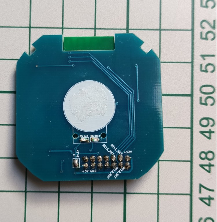
Let’s not forget – one does not need to use the final custom board that I made because this is the beauty of having a modular design. We can easily swap it with one of the other custom boards that I made or you can make your own as long as the hardware interface (that 2×7 pin connector) respects the standards from my schematics. What may change is the MCU GPIO pin assignments and that’s all.
Flashing the firmware
It’s all documented here but let’s tackle it a little bit also in this post. The whole project source code is based on the Apache MyNewt project so it follows its standards (well more or less but I tried to stick to it as much as possible).
I divided the source code files (and headers) based on the sub modules that the hardware part has like:
- Touch sensing logic
- LEDs logic
- Relays (actuators) logic
- Mesh logic
The touch sensing logic has to deal with reading the capacitive touch sensor signals and act accordingly on the actuators or the relays. It also deals with debouncing.
The LEDs logic is pretty simple and self explanatory – it only triggers the leds.
The relays logic deals with triggering the latching relays by creating the necessary pulses and it also keeps relays or better to say light channels state in memory (like which channel is in the ON or OFF state). The thing is that the power supply board has a feedback mechanism in order to see in what state the system is when powering on as well. So I did this in a simple way by keeping state in some variable stored in RAM. It’s a simple approach and it works. Another important thing to mention is that the relays logic has a a dedicated safety mechanism created in software so that whenever there is a power outage it will always force the system in the OFF state when power comes in. This is needed because the relays used on the power supply board have memory so you don’t want the lights to turn ON on a power break and maybe you’re not home. This make also the system predictable as I will know that it will always start in the OFF state on a power cycle.
The mesh logic has to do with the networking stuff and it’s the biggest part but not that big as the Apache Nimble project took care of most of the details for us in the background. The source code structure is pretty standard and I just adapted one of their examples to my needs. So before trying to understand the code I strongly recommend to study the Bluetooth mesh primer from the Bluetooth SIG website. It’s very well documented there and not bloated with lots of not so useful explanations.
What we’re most interested in here is the handlers of messages which trigger these two functions in the code: gen_onoff_set_ack(…)/gen_onoff_set_unack(…) and gen_onoff_get(…).
The first one is called whenever there’s a new message addressed to us and containing the ON/OFF payload (which is a 1 or a 0) because we’re using a GenericOnOffServer model. The other one as the name implies is when a GenericOnOffClient requires us to give it our current ON/OFF state. And yes as I mentioned in this post somewhere we do have a client/server architecture in this mesh networking system which must be familiar to you.
The other stuff in the source code deals with defining the required models that this light switch node has to offer and the Bluetooth subsystems initialization, etc.
Building the project
Apache MyNewt has a pretty cool build system and ways of organizing/structuring the source code by following a well defined pattern. I do recommend reading the concepts first in order to accommodate.
What I added in my case is:
- Custom BSPs.
- The main application.
- Custom targets.
Let’s build now the source code for the 1 channel custom board that I made. Here are the required steps using a Linux shell terminal (can be flashed from a Windows command prompt or PowerShell also):
Bootloader (this is the same for any channel variant). The following lines are flashing and loading the bootloader on the custom board:
newt build nrf52_custom_ts_boot
newt load nrf52_custom_ts_boot
Main application now. The following lines are flashing and loading the main application on the custom board:
newt build light_mesh_nrf52_custom_ts_1ch
newt create-image light_mesh_nrf52_custom_ts_1ch 0.1
newt load light_mesh_nrf52_custom_ts_1ch
For flashing the board one needs a standard CMSIS-DAP programmer – I’m using a stlink v2 clone reflashed for CMSIS-DAP compatibility. The interface is a standard SWD one so nothing special here (any CMSIS-DAP adapter can be used even a standard st-link clone which I think requires some modifications).
Provisioning/Configuring the mesh network
First we need the Android app (there should be an IOS version also). It’s important to leave one node to act as a Proxy at a minimum. This is the default state also when a new node is flashed for the first time.
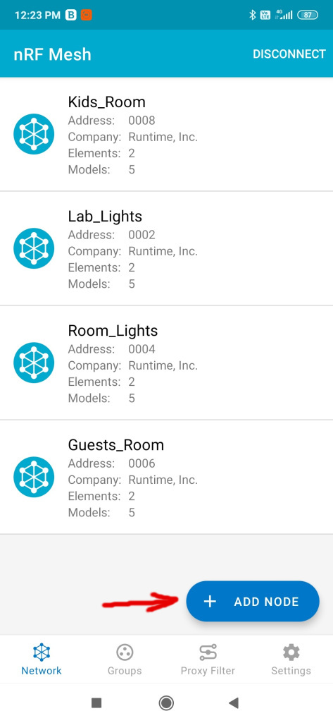
Initially the network is not formed as we don’t have any nodes provisioned at all so the first thing to do is to “Add” a new node by using the big blue button from the main application screen.
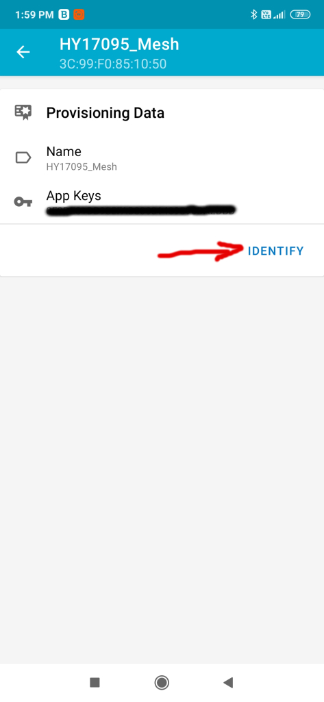
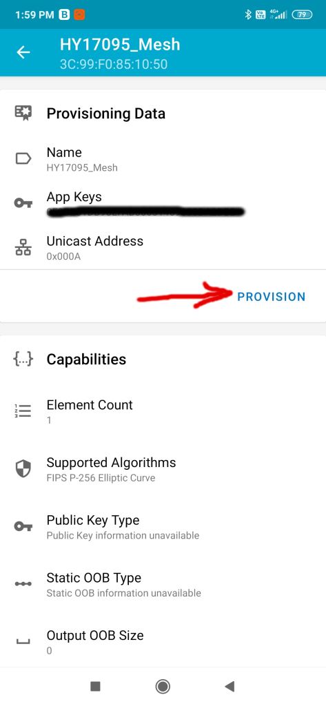
The unprovisioned node should appear then in the next screen. We click on it and then hit “Identify” and “Provision“. The whole process should not take more than 10s or so. You can also edit the node name afterwards – this is not relevant for the process or for the app it matters only for us the humans to know what purpose it has.
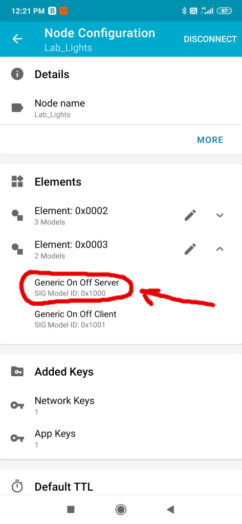
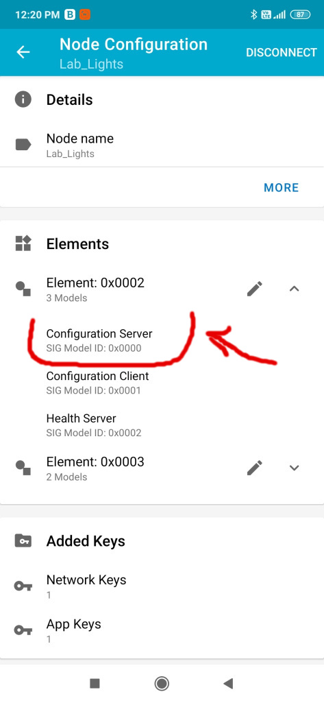
Next we need to configure the Generic OnOff server (this represents basically the light that we want to change its state to be either on or off) and bind an application key to it. Yes everything is secured in a Bluetooth Mesh network. There are separate keys used to encrypt and identify traffic both at the network level and the application level. So please be very careful not to share the keys or make them visible. You can also configure subscriptions here – in may case I created to groups beforehand (can be done from the application also). I can subscribe to more than one group and receive commands from both. In my case I have a specific group for where the lights are located and the other one is “All” so that I can act on all at once if I want to.
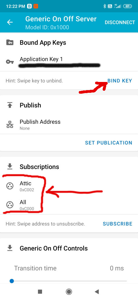
Then in the groups screen you can play with the lights and turn them on or off based on the associated group – trust me this is so cool! Then when I leave my house I can set an automation to turn everything off for example. Or I can set another light switch which is near my main entrance to act on the “All” group and turn off all the lights like that. I can do this by subscribing its Generic OnOff Client to publish to the “All” group – isn’t that cool? Oh and all the settings that you do when configuring the network are persistent (using the MCU internal flash memory).
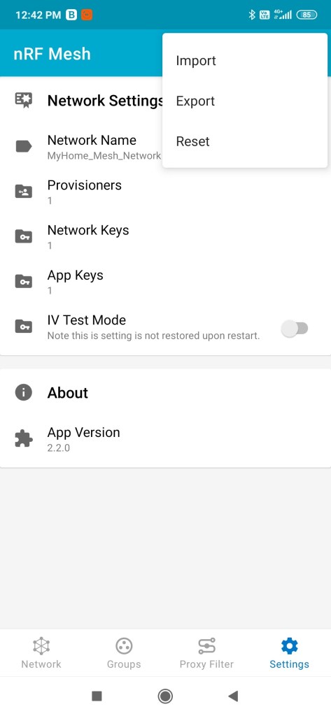
The next step after configuring the network is to back up the settings from the application by exporting them somewhere safe. This is an important step to do after you configured the network because the application won’t retain those settings if you change the phone, reset it or uninstall it. Why is this needed? Because the topology of the network, node id’s, application and network keys, groups, etc are saved in a json file which it reads upon start. Sorry but we don’t have network discovery or stuff like that yet. The mesh network will work without this part or without the phone but you won’t be able to reach it via the proxy node(s) because you don’t know or have the keys, etc… so keep this important back up step in mind. You will be able to import or re-import it later if desired.
Another thing you can do is tune the network settings like the number of retransmits and interval for messages both at the network level and for nodes.
I didn’t mentioned but the Bluetooth Mesh uses internally a mechanism called managed flooding. This means that messages are not routed by a process which results in them being transmitted along a specific path comprising a sequence of only certain devices. Instead, all devices in range receive messages and those which are acting as relays, retransmit the message to all other devices in range. All packets include a field known as the TTL. This may be used to limit the number of hops that a message takes as it is relayed. Heartbeat messages, transmitted by devices at intervals, include information which allows the network to learn about its topology and the number of hops away, each of the other devices is. This allows devices to set TTL to an optimal value, which avoids messages being relayed an unnecessary number of times.
From the nrf mesh application one can tune the above mentioned stuff as seen here:
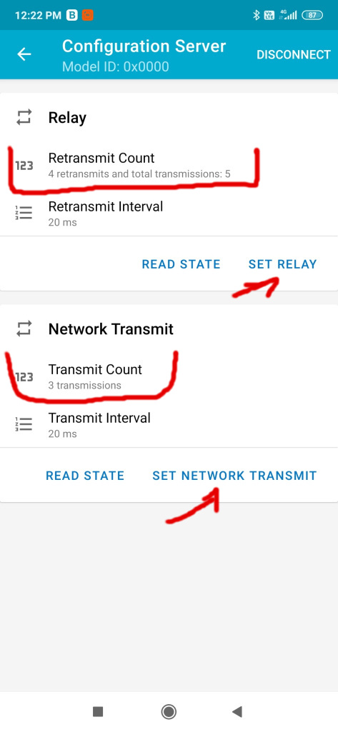
Basically you can tune the number of retransmits to suit your environment but don’t go very high as this increases the traffic and the collision rate of messages. This helps if the environment is a little bit noisy or if metallic obstacles are present in the walls, etc. I had to double in my case the number of retransmits from 2 to 4 and increase by 1 the network retransmits. But again as I said earlier this needs to be tuned for each environment. Oh and these settings are persisted on the nodes and it’s a per node setting. Other things to consider is the number of relaying nodes and where those are placed. In my case I configured all the nodes to perform relaying but it’s not necessary. You can disable relaying from the firmware at compile time or from the app as seen in the pictures above by pressing the SET RELAY button and configure the retransmits counter to 0.
Further documentation about the bluetooth mesh networking and lots of interesting stuff can be found on the official Bluetooth SIG page here and here which I do recommend reading as well as other articles on that subject present there.
Lots of things to discuss about this project and mesh networking but I think this will suffice for now.
In the next post I will be talking about the power supply design which was the most challenging part for me. Let’s not forget that this is the most important part of every electronics project in this world and also the most overlooked part! Do you agree with me?
To be continued…

One thought on “Intelligent light switches – Part 2”