At the beginning there was darkness lots of darkness until intelligent light switches appeared and suddenly things started to change and make people lives much more “brighter. OK enough storytelling … because I don’t believe this and neither do you.
A friend of mine asked me if I could automate his home lights so that he could switch the lights on and off at its will and in each room independently. I replied – why not? I like to automate stuff more than anything so this was an opportunity for me to put some things into practice. More than that I thought – pff, light bulbs ON, OFF, ON… that should be a piece of cake, right? Well… the reality turned to be a little bit different.
Requirements:
- First and the most important one – we should integrate with the existing infrastructure
- Touch sensors
- Radio control and feedback
Let’s take each of the above and discuss in detail:
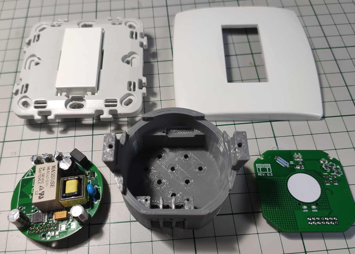
- Infrastructure: Here in the EU we have classic mechanical switches and a simple wiring in the walls as we don’t need more than that. So starting from the main panel from where all the “electricity” is distributed in the house we have this:

So how can one replace the above mechanical switch with an electronic one (with touch sensors, radio, bla, bla …) and keep the existing wiring/infrastructure? Well some of you might say it’s impossible – how to power up an electronic device using only the live wire and close the circuit via the light bulb back to neutral.
Making the impossible work ?
After some while of searching and doing research I found out that the magic works based on some preconditions:
- Having two power supplies – yes two are needed: one for the OFF state (stand-by) and one for the ON state.
- The electronic switch must draw very little current in the OFF state and this is achievable based on the fact that every light bulb has some leakage current because of the electronics inside it (CFL or LED bulbs) and for the incandescent ones – the electric resistance of the filament. Basically we steal some energy this way in order for our custom circuit to be always powered.
- In the ON state – this is the happy case because when the circuit is closed there’s enough current to make all work but there must be a low and sufficient voltage drop across our custom electronic switch so that it has again enough power to work.
First inspiration – Livolo ?
Let’s talk about the Livolo switch construction details a little bit. It has two boards inside it:
- One for the power supply and relays
- One for the touch sensing part and LED signaling
There’s a variant which has a radio receiver in it also – which is more expensive but it doesn’t provide feedback because it only has a radio receiver and not a transceiver so not good for us (things changed meanwhile and now they provide a ZigBee solution but not very cheap).
What we can do about it? Well the first and obvious thing to do is to replicate the front board with a custom one which has touch sensing support and BLE in our case and make it work and behave according to our needs.
Now we have so many options out there in choosing a radio solution and a microcontroller but not all of them are good for our project here.
Why ??? Well… because:
- We need a MCU combined with a radio transceiver that draws very little current (ideally a few milliamps on average and even lower)
- We need good software support and open source is a must
- We need a low component count in order to reduce complexity, cost, maintenance, deal with space constraints …
What I tried and experimented so far:
- A custom solution made by me using Arduino boards and custom software/radio protocol over radio transceivers low level libraries(I tried RFM12, NRF24L01, RFM69, and many others) – I gave up because it needed too much work for one man and it wasn’t very reliable (the software part and my custom protocol – which worked to some degree so hey it wasn’t too bad in the end because I learned some more stuff too)
- Next there was ( and still is actually) the great MySensors project – this one worked very great for me to some degree but when it was put into practice along with Livolo switches and other actuators where high reliability is desired… well it was not doing so well in my case.
- And the final step and last thing that I tried – BLE. In the end it turned out to be the most reliable way of making this switches work as expected and not crash so yeeyy! For this one I used the almighty NRF51822 RF SOC chip from Nordic Semiconductor – thank you Nordic Semiconductor for creating this – it’s really a great chip. More than that it’s supported by the ARM GCC toolchain and by the Arduino community which is a big plus – oh my – dreams start to come true.
Some pictures of some custom front boards that I made using NRF5xxxx based modules from various vendors:
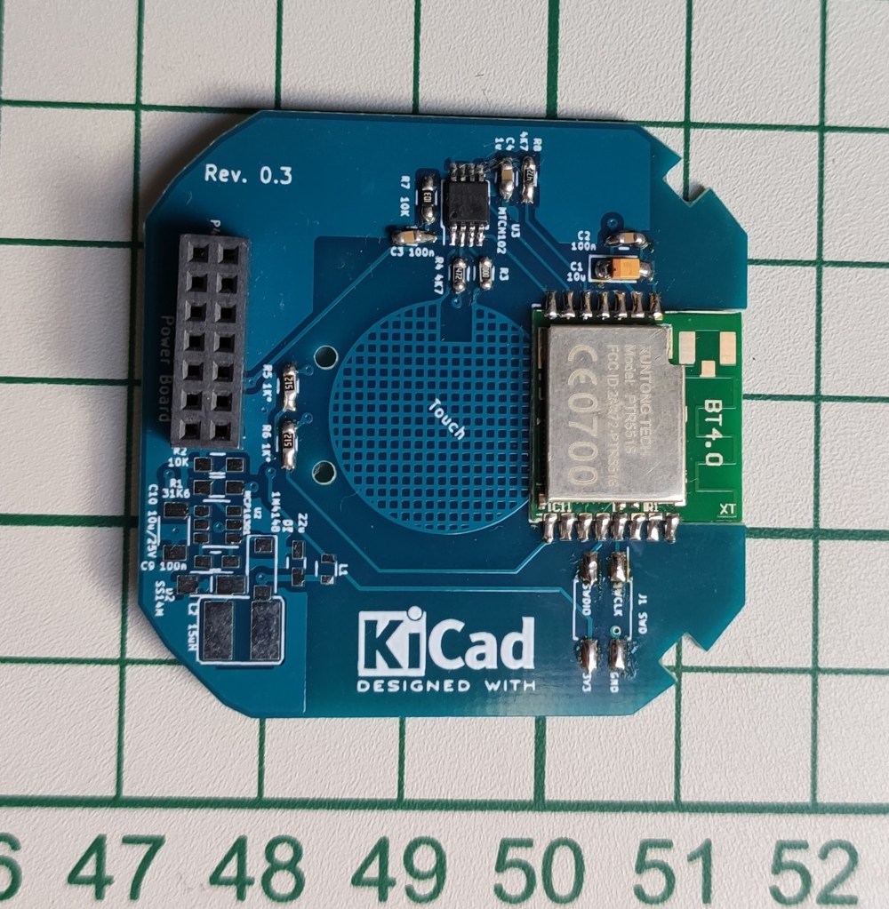
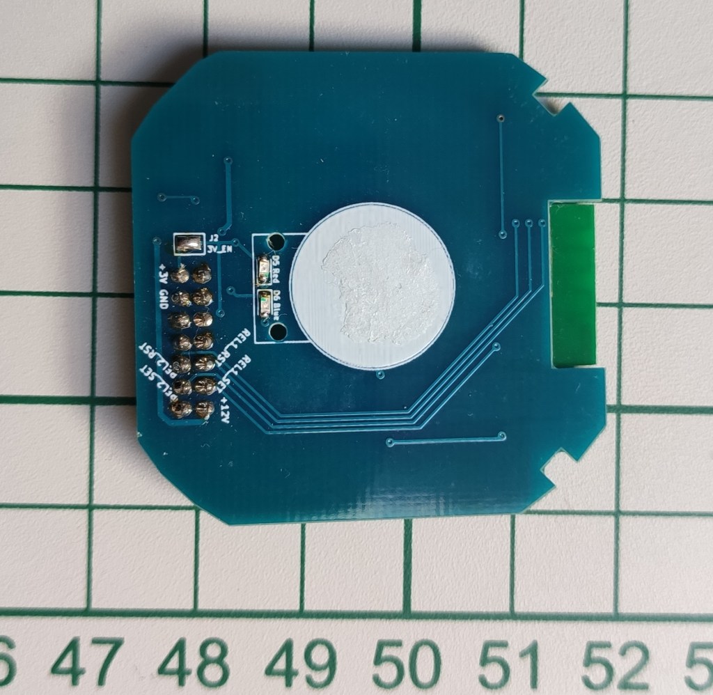
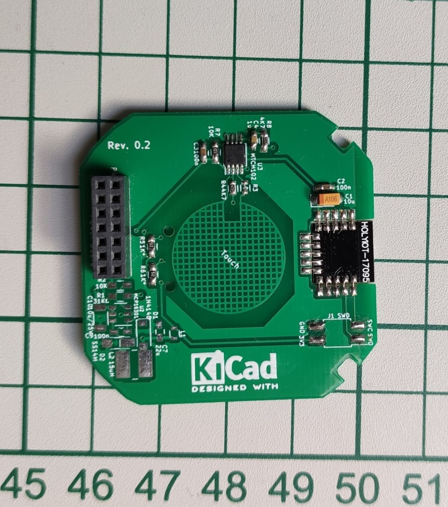
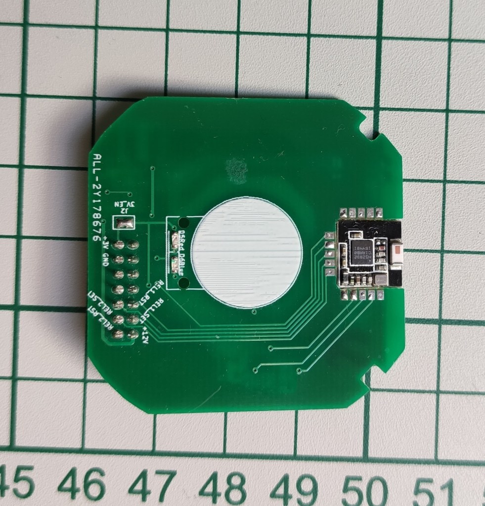
All the above modules work and have been tested with real Livolo switches. More details can be found on my GitHub projects page based on the module type and number of channels here.
In the next post I will describe in a little bit more detail the control board used in this project using a custom designed that I made. This is the final design on which I settled using the almighty NRF52832 chip.
To be continued …
